
Yes, that's right. After gathering all the materials I built my first little railgun experiment.

Read the whole article after the break!
Let's first take a look at how a railgun or magnetic accelerator works, a video about the whole topic can be found here.
Similar to a coilgun, a railgun works by magnetic propulsion.
A basic railgun consists of three parts: A set of parallel, metal rails, a huge powersource like a capacitorbank and a metal projectile. Here is a railgun's schematic for your convenience.
 What happens inside this small scale railgun experiment? There's a huge current flowing through the rails and the projectile at the same time as shown in the illustration. Every current, or on a smaller scale, every moving charge creates a magnetic field. Take your right hand and form a fist - thumb in the current's direction - your fingers now indicate the magnetic field lines created by the current in your thumb's direction. Why is the projectile moving then?
 According to Lorentz's law, every charge (red current) moving in a magnetic (blue) field experiences a force (green).
So basically the magnetic field emitted by electrons travelling on the rails propels the projectile. Before we will take on real railguns let's do a small scale experiment first.
 These are two aluminum strips glued onto a piece of cardboard. Additionally I connected a 9V battery's plus to one and minus to the other rail. Our small scale projectile is a metal stick with two small, round magnets on each end. The magnets are just here to amplify the effect and can be ignored right now - the experiment also works without the magnets as you can see in the video above.
 Drop the projectile touching both rails and it will start accelerating towards the end of the rails.
What does this small scale experiment reveal about railguns' physics? First of all you can see sparks flying deteriorating the rails, just as in a real high power railgun. Secondly the projectile gets hot due to the current flowing through it and its electrical resistance - again a great similarity to the real deal.
And last but not least, the projectile has to enter the railgun with a initial velocity, because otherwise it would get welded into place not accelerate at all.
So what's the plan for a small scale railgun experiment?
In order to achieve a high current through rails and projectile we need a huge, high amperage powersource: A capacitorbank. Since a railgun is basically a big short circuit, normal batteries and transformers wouldn't work well due to their inability to provide enormous high current peaks. The best solution for this low cost, homescale railgun experiment is a capacitor bank. My capacitor bank consists of three 2200uF at 400V capacitors in parrallel:

 Most capacitors already have threaded poles, which is very useful connecting many capacitors via metal sheets as you can see in the picture above.
The rail setup consists of two metal rails sandwiched in between to PMMA acrylic sheets. Since the rails experience a lot of force during an acceleration test, they have to be secured tightly with screws to the acrylic sheets. Here's my setup before and after screwing it together:

 Now I had to decide wether to connect the capacitor directly to the rails, creating a "hot rail" railgun design, or to use some kind of high current switch.
I chose to stick with a "hot rail" design for two reasons: Firstly I simply did not have any switch or semiconductor that would withstand such high currents. Of course there are switches and semiconductors which would, but they were way too expensive for a small scale experiment like this. The second reason was, that the projectile needed to enter the rails moving anyways, so there was no need for a switch. The projectile itself would connect the rails acting as switch.
So here you can see the "hot rail" design.
 The next challenge was to find a mechanism which guides in the projectile with an initial velocity. Most professional railguns use compressed air but I came up with a much simpler and cheaper method - a spring loaded lever:
 The mechanism works pretty straigth fordward. Once released the spring loaded lever pushes the projectile between the rails:
 Let's take a closer look at the projectile. It is made out of metal and I chose a V-shape so it would be able to bend at least a little bit and compensate small unevenness. A piece of aluminium foil should also work fine.
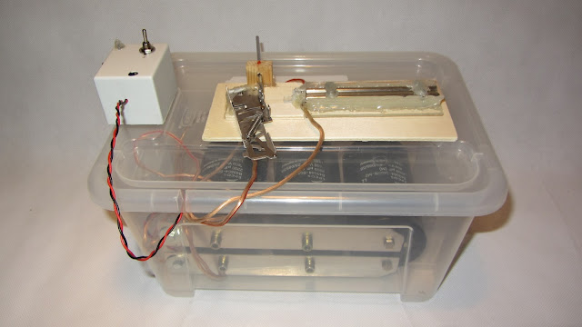
 The last step is charging the capacitors with the help of a little 400V DC transformer. The complete setup can be seen here:
 Here is a slow motion gif of an acelleration at 400V.
 This is what the rails looked like after an accelleration test:
 There's a video with a lot of footage testing the railgun experiment, of course:
Let's first take a look at how a railgun or magnetic accelerator works, a video about the whole topic can be found here.
Similar to a coilgun, a railgun works by magnetic propulsion.
A basic railgun consists of three parts: A set of parallel, metal rails, a huge powersource like a capacitorbank and a metal projectile. Here is a railgun's schematic for your convenience.


So basically the magnetic field emitted by electrons travelling on the rails propels the projectile. Before we will take on real railguns let's do a small scale experiment first.


What does this small scale experiment reveal about railguns' physics? First of all you can see sparks flying deteriorating the rails, just as in a real high power railgun. Secondly the projectile gets hot due to the current flowing through it and its electrical resistance - again a great similarity to the real deal.
And last but not least, the projectile has to enter the railgun with a initial velocity, because otherwise it would get welded into place not accelerate at all.
So what's the plan for a small scale railgun experiment?
In order to achieve a high current through rails and projectile we need a huge, high amperage powersource: A capacitorbank. Since a railgun is basically a big short circuit, normal batteries and transformers wouldn't work well due to their inability to provide enormous high current peaks. The best solution for this low cost, homescale railgun experiment is a capacitor bank. My capacitor bank consists of three 2200uF at 400V capacitors in parrallel:


The rail setup consists of two metal rails sandwiched in between to PMMA acrylic sheets. Since the rails experience a lot of force during an acceleration test, they have to be secured tightly with screws to the acrylic sheets. Here's my setup before and after screwing it together:


I chose to stick with a "hot rail" design for two reasons: Firstly I simply did not have any switch or semiconductor that would withstand such high currents. Of course there are switches and semiconductors which would, but they were way too expensive for a small scale experiment like this. The second reason was, that the projectile needed to enter the rails moving anyways, so there was no need for a switch. The projectile itself would connect the rails acting as switch.
So here you can see the "hot rail" design.


